The orbiter
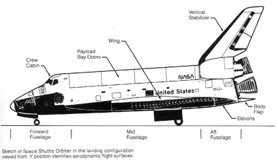
The orbiter is made of nine main parts: the front fuselage with its upper and lower deck of the cabine for the crew. The wings, the central fuselage with the payload bay and the doors. The rear fuselage, the front steering system, the vertical stabilizer, the body flap, the rear steering system and the SSME engines. The major systems are made from aluminium alloy and protected by a heat shield.
The cockpit - Nose
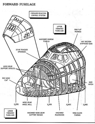
The front fuselage is made of 2024 panels of aluminium. It is made from two hulls one in another. The cabine is made of frames, girders and preservative of aluminium which goes in the lower part of the fuselage. The lower part shelters the front landing gear and the hatch for the crew. It is supported by the front fuselage and four strengten points. This compartment comports one hatch (explosive) on the left side, for the entrance and exit of the crew, and one hatch on the rear wall for the EVAs. The cockpit has eleven portholes, six on the front, one on the hatch and two on the top. They are made from one piece of glass of very good quality (alumino-silicat) which helps to strengten the cockpit. They are 1.5 cm of thickness and are covered with an anti-IR layer. The two centrals portholes are thicker (3.2 cm) and made of silica. The one on the top are less thick (1.1 cm) and the one on the rear wall are 0.7 cm thick.
On-board computer
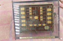
The on-board computer of the orbiter are IBM AP 101 modified. They are programmed in assembler and in FORTRAN. they have a memory RAM of 3 833 856 bits, 106 496 words of 16 bits. Moreover their is a database of 34 MBits on magnetic tape where the flight program is memorized. This flight program is about 15 MBits (1000 instruction paper sheet).

The memory left is used to stock other informations. The parts of the flight programme is loaded in RAM as needed during the mission, divided into 9 parts which is the different parts of a mission. The computer in cadenced at 3 MHz, during the orbital flight only one computer is on. But during critical phases all the computers are on (5 in total). Four computers receive the information from the sensors of the orbiter and the boosters. They make the same operation and synchronize together (to 440 times per second), the last one is the judge he take the decision and act as a backup if the other computers fail. The algorithms are coded by different teams and in different langages to avoid mistakes.
The dashboard
The dashboard of the orbiter is made from aviation with improvement for space flights.
Dials, switches and 3 computer screens (CRT) helps the pilot to monitor all the on-board systems.
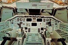
Those three screens are connected to the on-board computer and each crew member can display the information he wants on one of them if required.
The Rotational Hand Controller is used to control the three axes of the orbiter. During the ascent it can be use to control the SSME's and SRB's tailpipes. During the putting into orbit and for the de-orbiting it controls the OMS's tailpipes and the thrust of the RCS. Into orbit it control the RCS. During the re-entry, it controls the RCS and the aerodynamic actuators. It also be used to operate the RMS (arm) into orbit.
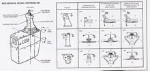
Pedals of tool yoke allow the pilot to change the direction of the vertical stabilizer and/or to use the air-brake for the landing approach.
The wing
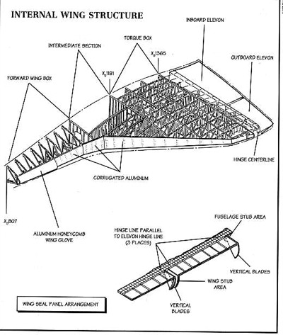
The 2 wings of the orbiter are making a delta wing. It is made of 5 parts, the apex, the middle part with the landing gear, the torque box, the protection of the elevons and the elevons. The wing is light with longerons and lot of strengten pieces. The external coating has also a tighten function like a honeycomb. The lower and upper sides are covered up with heat shields. Each wing measure 18.3 m long and 1.5 m of thickness. The elevons at the end of each wing can move fomr -21.5° to +36.5°. They are from honeycomb structure in aluminium and divided in two parts to minimize the strength on the wings's hinge.
The payload bay
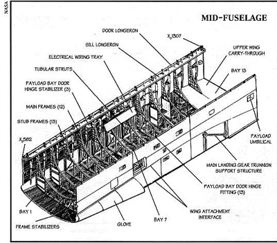
The central part of the fuselage is 18.24 m long. It's the main part of the orbiter where all the other are plugged (the cabin, the rear part, the wings). The central part is made for the payload bay. It's 18.2 m long and 5.2 m width it is made of strengten beams. The uppers beams are used for the joint-frame of the payload bay doors (13) and for the RMS (Remote manipulator System). This doors are made of epoxy and weigh 1480 kg. The cooling system is located on those doors it is used for cooling the on-board systems, the weigh is 6124 kg.
The remote manipulator system
The Remote Manipulator System is plugged on a side panel (left side) of the pyaload bay. The shoulder is on the front (near the cabin) and 15.3 m long (35.7 cm of diameter). It is fasten by three points on the payload bay. It could have been plugged on the right side of the Orbiter but it has never be done because the Ku antenna must be moved. Only one arm can be controlled by the crew (rear wall), even if the wires are already plugged to control two.
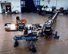
Its weight is 411 kg on Earth (carbon fibre), it can move payload of 29 tons in orbit. But it can't move its own weight on Earth, so to test it, it was lay on wheels. Equipped with video camera (one on the elbow and one wrist), it can move payload, bring them back or even act as a ladder for the astronauts during the EVAs. Finally, due to its high mobility it can also be used to look at different parts of the Orbiter.

The vertical stabilizer
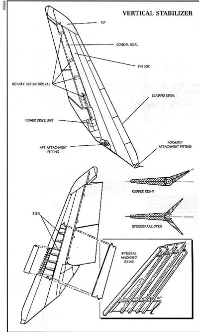
The vertical stabilizer ensures the stability and the direction of the orbiter in flight. It supports the mobiles elements which are used to oriente the orbiter or to slow down (areobreak). These last ones are jointed with four pieces and controlled by an electrical engine. The box of the vertical stabilizer is made of two strengten pieces mashin-finished from one piece, panels. The box is settled to the rear part of the fuselage by ten bolts. The mobile parts (direction and aerobrake) are made of aluminium alloy and panels in honeycomb structure.
The engines
The OMS (Orbiting Maneuvring System) is used to put the orbiter on the working orbit, the Rendez-Vous and the de-orbiting. The system is composed from two pods (one on each side of he shuttle). The fuel used for the OMS is MMS and N2O4.
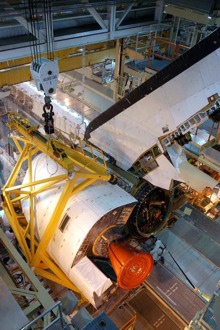
The RCS (Reaction Control System) use 38 main engines and 6 verniers for the orbital manoeuvres, the flying phases and the re-entry. They can be use above 21 km of altitude.
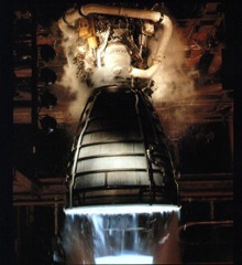
The SSME engines (Space Shuttle Main Engines) are particular because the mass ratio was highly decrease. Saturn 5 had a ratio of 20, for the Shuttle it is 15.
The SSME engines are switched on from start and cut-off once in orbit to limit the dead mass. They use liquid Hydrogen and Oxygen (which iss highly powerful) and moreover they function with close cycle scheme so they have an increased power. The thrust of one engine is 213 tons on sea level and 170 tons on vacuum.
Landing gear
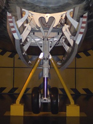
The landing gears of the orbiter are conventional. It has three landing gears, one under the nose and one under each wing. Each leg is made of very resistive high steel with a pneumo-hydraulic shock absorber ended by two wheels. A protection of cadnium-titane and a painting of urethane protect the landing gear during the orbital flight. The traps of the housings are coated by tiles. The landing gears deploy in ten seconds at 76m high and a speed of 623 km/h.
Heat shield
The materials used on the orbiter are passif (it means there is no cooling system). They are selected to resists high temperatures and to be light. On the first orbiter (Columbia) four materials where selected, the reinforced carbon (RCC), tiles of silice for high and low temperatures LRSI and HRSI, and plates of FLRSI. Later other materials were developed on certain zones like insulating coats.
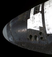
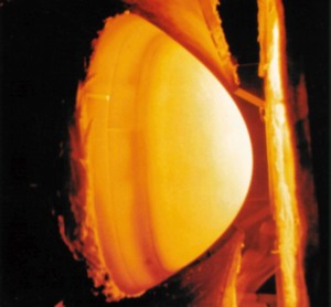
The Reinforced Carbon Carbon (RCC) is made of composite carbon, grey. It is melted with isolating layers of inconel (metal) and plates of quartz to protect the lower part of the orbiter where the temperatures are high, more than 1260° (cabin, body, wings). The nose is protected by a shield made from one piece of 1.5 m diameter, the leading edges of the wings are protected by 22 panels in U bolded to it. The RCC covers 135 m2 of the fuselage.
The HSRI (High Reusable Surface Insulation) tiles are used on the all the underside of the orbiter and around the portholes of the cabin. Some HSRI tiles are also used on the leading edges of the vertical stabilizer, the underside of the body flap and the elevons. They are used when the temperature is under 1260°C. Those tiles are black.
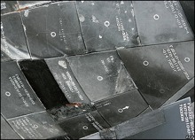
The LRSI (Low temperature Reusable Surface Insulation) tiles are used where the temperature is low (under 650°C). They are used on the upper side of the fuselage, of the wings and the vertical stabilizer.
Each tile is unique and has a serial number to put it in the exact place on the shield. The LRSI and HRSI are made of very fine silice (99.9%) and air (9/1). The upper side and the sides are covered by a glass layer made of borosilicate. The main quality of those tiles are their high coefficient of emissivity near black body (0.85), it means that they offer a good dissipation to the heat and a good absorption to solar radiations. The main problem is that they are very weak to mechanical constraints and can be broken with a finger.
Thirdly, the Energiya was an expendable launch vehicle but the U.S. Shuttle was designed with in mind since its main engines are the orbiter and the SRBs are refurbished each flight. NASA's rationale for reusability was it would enable quicker turnaround for launches then in turn, higher flight rates, and costs per flight. Unfortunately, the U.S. Shuttle never achieved the high flight rates that envisioned and remains an expensive way to payloads into space. Whether the Soviet decision go with the Energiya ELV booster was most cost-effective is difficult to assess since only flew twice. In addition, contrary to Soviets' traditional tendencies, they did not simply an existing rocket, although they did closely the U.S. orbiter s configuration.
The Soviet Energiya-Buran story is considerably less well especially in the English language literature While few glossy monographs cover the Energiya and Buran separately, they are not very analytical. is a considerable amount of relevant Russian material on the Soviet Shuttle and some it exists in translation. Even in Russian, there seems to be no definitive analytical of the Buran that covers the political behind its development rather than simply the details. This remains as a very worthwhile potentially fascinating task for an interested scholar Russian language skills.

