Aerofoil of Buran
The structure of Buran wich made it flight is called the aerofoil, it is composed of aerodynamic shaped, which supports the constraints during the flight, and includes the systems and the elements ensuring the descent and the landing. Its mass, including with its systems, makes nearly 40% of the starting mass of Buran. The structure of the aerofoil (without the heat shield) ensures the arrangement and the protection of the crew, the payload and the various systems during all the stages of the flight. The aerofoil includes:
- the hermetic module of the cabin for the crew;
- the nasal part of the fuselage, panes and the entry trap door;
- the payload bay whose leaves open, plus the ventilation leaves, transmission nodes with Energia;
- the part of tail of the fuselage, with hang fixings of the vertical stabilizer, the transmission nodes with Energia, the propulsion system and the leaves of ventilation;
- the balancer shield;
- consoles of control of the wing with the aerodynamic bodies (ailerons), the leading edge, and the residences for the landing gears
- the vertical stabilizer made up of the drift which has also the function of air-brake;
- fasteners of the apparatuses, the equipment, piping, cables, etc.
The presence in the central part of the fuselage and at the beginning of the wings of the ventilation system asked for the introduction of additional elements to rigidify the structure.
At the time of creation of Buran, it was decided to create a "cold" heat shield for the interiors parts of the sailplane (-130 with +160°C), moreover the nose and the leading edge of the wings are covered with a resistant matter to heat containing carbon and of thermal barriers for the connection zones with the main structure had to be elaborate.
The elevons of the wing are composed of 2 parts (interior and external), they are fixed by 3 points of fastener at the back of the wing. Each section is controlled in an autonomous way by a mechanism located in the wing, ensuring an angle of beat of 35° to the top and of 20° downward.
The nose
The nasal part of the fuselage have a length of 9m, a width of 5.5m and a height of 6m, contains the cockpit, the zone of life (lower level), the engines and the on-board equipment.
The nose is highly solicited by the rise in temperature at the time of re-entry in the dense layers of the atmosphere, it is covered with a heat shield composed of carbon and mechanically reinforced by 5 strengthening pieces to rigidify the structure.
The higher part includes beams of reinforcement, the port-holes and the trap doors. The mechanical reinforcements are composed of 7 strengthening pieces. Moreover, 6 port-holes out of quartz glass are assembled on the front, 2 trap doors for damages (catapult-launchings) and 2 top port-holes.
The lower part includes the beams of reinforcement with holes to insert the antennas of navigation and the radiotechnology unit, protected by radiotransparentes plates.
The cockpit
The module of the cabin of 5.4 m length , more than 5 m width and of 5.4 m height entirely in metal and hermetically welded, shelters the control unit of the crew, the electronic equipment of piloting and SGO equipment. The body of the cabin includes an outside envelope, six beams of reinforcements, the dividing fronts and back walls and is composed of "corrugated" panels manufactured by the milling of aluminium welded alloy plates then sets together. The structure is reinforced by beams at the place of the trap doors and port-holes of glass because of the variations of curve of surface.
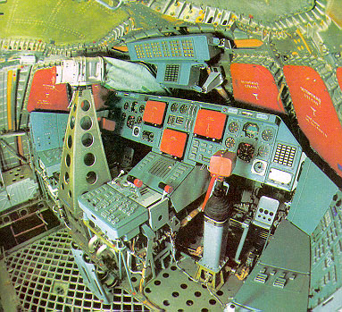
The entry trap door, which opens towards the interior, ensures the access to the livable section. On its lid is fixed the fast mechanism of closing made up of 10 bolts. 9 port-holes in the piloting section ensure a sufficient vision area for working on orbit and manual piloting during the re-entry in the atmosphere and the landing.
High requirements about the life-span of the elements were required, in particular because of the deformation and load transfer during all the stages of the flight. This requirement is ensured by the suspension of the cabin by a articulated levers device laid out in the zone of connection of the envelope and the front floor.
The main problem which the engineers of the cabin faced was its sealing. The length of the hermetic joints is 153 m, the number of joints for the port-holes and the openings are 1018 and the length of the condensation joints of the envelope (with the double barriers of condensation) is 142 m. Moreover the permissible leakages of air of the cabin were not to exceed 1.5 kg/day, which is equivalent to an opening of 0.35 mm in diameter.
On-board computer
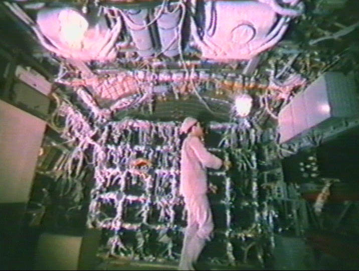
The on-board computer receives the information from on-board sensors, treats the information according to the various tasks and sends the corresponding orders to the actuator. To guarantee the real-time functioning the reading / writing of inputs / outputs is made every 32.8 ms.
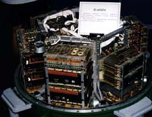
The structure of the on-board computer is defined by keeping the working capacity as well as guaranteeing the crew safety. The on-board computer consists of 2 parts: the central and regional treatment, made of 4 computers each which work in a synchronous way and treat the same tasks. The 4 treatment's units make the same operations, the results are compared at the end of the process, if a computer falls out of order it is automatically shutdown (the 3 others keep working) etc. until there are no more than 2 computers, if a breakdown arises (the results of the 2 computers are different) the system "decides" to randomly shutdown a computer so that there is always 50 % of chance to function.
The synchronization of the information of the 4 real-time treatments units is a difficult operation and no reliable. So, the synchronization of the central and regional modules is not made in a software way (as on the American shuttle) but by hardware, there is a single quartz clock which generates the impulses for the 8 treatments units at 4 MHz. As the clock has to answer the requirements of reliability (taking into account 2 hardware failure) it has 5 channels which are reserved for the clock signal on which it is established the vote rule of "3 for 5". The storage of the information of the on-board computer is made on a tape with a the storage capacity of 819 200 words of 32 bits of which a part for the software before its load in RAM. This strip could also be used to store information which will be printed on the on-board screens
The dashboard
The dashboard of Buran is divided into several parts, the navigation management system , the on-board systems, the management of stowing to the shuttle, the management of the payload carrying.
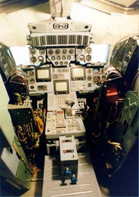
On all the Russian manned space ships, like on the Salyut and Diamants, the design of the dashboard is identical, and was developed by the same organization. Due to the great number of apparatuses the mass of the dashboard was 90 kg and exceeded of 13% the requirements of the contract conditions.
The wing
The wing of Bourane consists of 2 parts (right-hand side and left) which form a delta wing. Each half-wing has a angle located at the first third, the principal surface of the trapezoid is 250 m2 for a scale of 24 m. The middle part of the wing is ensured by the fuselage. The mechanical loads of the bearing pressure are reported towards it.

The structure of the wing is divided into several parts, the nose, the average part, the tail, the landing gear compartment, its trap door and the elevons. The structure of each wing include panels of reinforcement and the central girders.
The protective shields of the elevons include 16 sections. These plates of protection move along a "rail" thanks to a carriage and a roller connected to the traction system of the elevon. This mechanism ensures an optimum protection and a synchronous movement between the elevons and the plates of protection except on the slit along the contour of the wing where the plasma can infiltrate.
The connection of the wing to the fuselage is carried out using central girders, to which hole head bars are attached, whereas on the edges of the fuselage the nodes of fixings are pins. The welding between the fuselage and the wing is carried out by an aluminium alloy. Moreover the structure of the wing is relatively hermetic because all the weldings are continuous.
The payload bay
The central part of the fuselage has a length of 15.5 m, a width of 6 m, and a height 5.5 m and ensures the protection of the payload, the elements of the on-board system and their assembly. This central part is made up of 26 laterals panels and lower panels of the envelope, of strengthening pieces, the doors of the payload bay and the transmission centre with Energia.

The envelope of the payload bay is made up of side and lower panels divided into 4 parts in the direction of the length and fixed by bolts. The panels are welded together and a finer plates cover them on all the fuselage. The panels and the covering are standardized on all over the shuttle.
The central girders of the fuselage are located on the left and right sides and border the doors of the payload bay. Each one of them includes 2 parts, the divisions, and the stiffener, which will form the structure intended to absorb the loads applying to the fuselage. The outward-opening doors of the payload bay are firmly hung by bolts with the stiffeners.
The structure of the tail is made up of a rigidifying part and one not rigidifying. The rigidifying part includes the divisions, the beams manufactured in the titanium plates and perceive the constraints coming from the wings, of the vertical stabilizer and the junction with the Energia launcher; 2 of them are joined by 12 cross-pieces and will form the rigid structure which will absorb the mechanical constraints during the various stages of the flight. The other group supports the unit and ensures the external shape of the tail.
The remote manipulator system
The remote manipulator system of the Buran shuttle was worked out by the central institute of search and experiments for robotics and cybernetics (ГНЦ ЦНИИ РТК РФ) at St-Petersburg. This institution was created at the end of the Sixties from the engineering and design department of cybernetics.
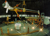
The tests proceeded at the institute in a special hangar. The arm is supported by cables to recreate the conditions of weightlessness. The arm of 15 m length (in the "tended" position of transport) moves in 3 plans and has 6 degrees of freedom. The handling system of the shuttle includes 2 remote manipulator system of 360 kg, the main and a reserve one. At the end of each manipulators is a grip which makes it possible to move the loads, moreover the operator see the handling thanks to a mobile camera (2 degrees of liberty) and with a projector fixed on the grip.
The management of the remote manipulator system is carried out by the console located at the back of the cockpit. Data-processing programs help the user for the complex handling tasks, Thanks to pre-programmed management modes. Management is ensured by 2 joysticks, one for the manipulation of the arm and the other one for the grip. In automatic mode the manipulator acts according to the programmed sequence, it fetches the payload in the hold and installs it outside the shuttle.
The remote manipulator system of the Buran shuttle has a major difference compared to the american one, it can not only be manipulated from the inside of the shuttle but also from the Earth. Management is made at the Terrestrial Flight Center, which downloads telemetric informations in the on-board computer which transmits them to the remote manipulator system. Thus, an operator on the ground can handle the payload at a distance of several thousands of kilometers in full safety.
The turbojets
Initially it was expected that all the aerodromes of the USSR can receive the shuttle, but quickly the authorities realized that that was impossible because the shuttle could have to land apart from the territory. There were then 2 solutions: increasing the number of aerodromes (but Buran was a military object, the strategic allies were laid out too closer to the borders of the USSR, whereas Cuba was too close to the adversary territory), or to increase the operating range by the addition of turbojets. It is the second solution which was chosen by the engineers.
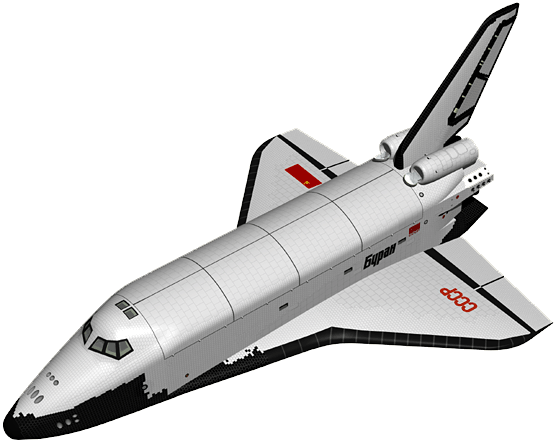
There was to be 2 turbojets on Buran, the same model of engine (ТРД АЛ-31) that on the Sukoï 27 plane. This turbojet develops a thrust of 12500 kgs in after-burning and 7700 kgf in maximum mode. The fuel consumption in maximum mode is 0.75 kg/(kgf*h) and 1.92 kg/(kgf*h), the minimal consumption of cruising is 0.67 kg/(kgf*h). The temperature of gases at exit of the turbojet is of 1665°K, the dry mass of the engine is 1530 kg, the length is 4.95 m, the maximum diameter is 1.18 m, and the diameter of entry is 0.905 m.
Engines was installed on both sides of the drift to the top of the rear part of the shuttle. Their presence strongly increased the distance covered at the time of the re-entry in the atmosphere and simplified the landing.
For the first flight of Buran the turbojets АЛ-31 were not still ready, the shuttle had to land in sailplane mode. Moreover the load capacity of Energia, of which it was the 2nd launching in autumn 1988, did not fulfill the requirements. The payload was too weak, which confirms the mail of the Chief's Assistant of the engineering and design department of Energia, Igor Sadovsky. This is why, by taking into account all the factors of risks related to the first trial flight of Buran, it was decided not to use the turbojets АЛ-31 for the first flight of Buran on November 15, 1988.
The vertical stabilizer
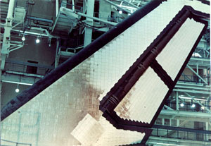
The vertical stabilizer ensures the stability and the direction of Buran in flight and includes the drift, the rudder and the bonnet cover. The drift includes the central girders, strengthening pieces and protective panels. In its upper part take place the electromechanical unit and the transmission antenna protected by a radiotransparante plate. The rudder can work either of rudder, or in air-brake during of the descent of the shuttle to reduce its speed, this is possible because it is composed of 2 leaves. The aperture of each leaf can reach 23° in direction mode and 43.5° in air-brake mode.
The engines
The motor unit is one of the main systems of Buran, it is used to equilibrate the launcher during the putting into orbit and for all dynamic operations during the space flight.
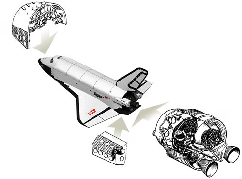
In the case of an undamaged flight, engines assure the separation of Buran and Energia, the movement of Buran on the working orbit (2 impulses), the stabilization, the orientation, orbitals operations, rapprochement and docking with other spaceships, the slowing down and the control of the going down.
Except for the purely dynamic tasks the propulsion system also assures the thermal auto-regulation, and the auto-control of equipments, as well as the integration with the electric supply system.
For the first time in the world the motor unit of a shuttle uses a cryogenic oxidizer (liquid oxygen) and one synthetic not cryogenic hydrocarbon with an improved efficiency. The use of ecologically clean fuel increased the specific impulse of engines, but needed the introduction on Buran of cryotechniques elements, because the oxygen is transferred and stored in the liquid state (the boiling point is -183°C). The difference between the 2 engines types is that the main engines work with liquid oxygen while the orbital precision steering system use gas oxygen.
Landing gear
The landing gear of Buran has the same function as a standard plane one (it ensures the absorption of energy during the landing and stops the shuttle).
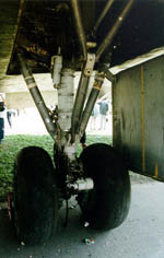
The landing gear produced at the factory "Гидромаш" consists of 2 supports laid out in an optimum way for the masses distribution, moreover on each support is located the telescopic hydropneumatic shock absorber and ends in 2 high pressure wheels.
Parachute
The installation of the parachute-brake is useful for the deceleration of Buran on the landing strip, to relieve the wheel braking system up to 50 t and to decrease the braking distance by 500 m. The parachute system includes, the pyrotechnical mechanism of the ejection of the lid, the fasteners of the parachute, the system of reheating and the automatic block.
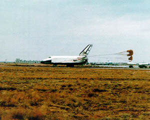
The ejection of the parachute is done in an automatic way when the 3 landing gears touch the track. The lid is then ejected and the 3 parachutes of cruciform form are spread. When the speed of the shuttle reaches 50 km/h the parachutes are detached.
To guarantee the correct operation of the parachute-brake system, heating resistances ensure a temperature of at least -50°C during the orbital flight, on the other hand during the descent the heat shield prevents the temperature from exceeding +100°C.
Heat shield
Extreme conditions of heat during the descent in the atmosphere forced engineers to find a solution to work out the heat shield. It will be constituted of superfine fibre of oxide of silicon (analysis of all the components of the shield shown that the radiation can be strongly weakened by using fibres of 1.5-2 microns), able to weaken the thermal radiation and increase the dispersion of heat to protect the structure of the aerofoil.
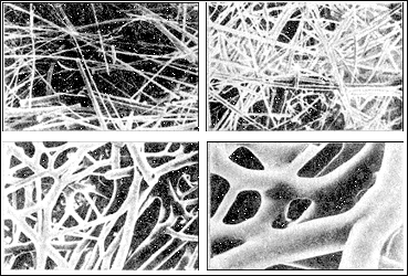
Various requirements were necessary for the heat shield, solidity of the tiles, lightness, resistances to high gradients of temperature, small thermal conductibility, high degree of blackness (0.8-0.9), oxidation resistance. All these points leads the engineers to create tiles containing quartz fibres.
In the zones of strong heat (higher than 1250°C), the nose, the leading edge of the wings, it was necessary to create a very resistant material containing carbon because the temperatures could go up until 1650°C. Whereas in the zones where the temperatures did not exceed 370°C the shield was made with organic compounds.
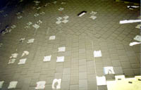
The tiles of the shields are stuck to an external cover fabric of 0.3 mm of thickness, which is also stuck to the fuselage. This layer of refractory fabric is used as heat insulator between the shield and the fuselage, and makes it possible to minimize the deformation impact of the shield on this last.
So that the contact between the tiles and the fuselage is most exact possible, the treatment program was corrected according to the measurements taken on real surface and according to 100 points of reference on each tiles. All the stages including the development of the documentation of study, manufacture and control were made on computer. After the assembly of the tile on the fuselage one came to test the tear away strength there. Lastly, a whole battery of machines came to test the solidity of the shield, laser, acoustic and neutrons guns, radiology tools, electronic microscopy, etc.
Clearly many configurations were possible for both Designers were obviously limited by certain of physics and by certain technical Social, political, and cultural factors strongly the selection of these technical goals, By analyzing which political factors and of national technological style were most to the design of the U.S. and the Soviet Buran, I aim show how these two space transportation are more distinct than they appear first blush. Such differences in turn emphasize the panoply of possible options imaginative designers could have used. By at how they winnowed their choices, case study should demonstrate the sometimes importance of technological style and the present influence of politics on the of engineering, specifically in the space
A second important difference is that Buran only an orbiter and relies upon Energiya launch vehicle and four liquid boosters to get into orbit. The Shuttle, on the other hand, has main rocket engines in the orbiter along with two solid rocket boosters Buran used the space occupied by U.S. Shuttle's main engines to house engines for go-around capability on landing, the U.S. Shuttle does not have.10 short, the Buran was only one payload that the Energiya could lift space, while on the U.S. side, orbiter is an integral part of total Shuttle launch system.

